Guest Column: How can transit agencies optimize the design of their facilities for overhead electric bus charging?
Transit agencies are adopting electrification for the sake of environmental stewardship, with the added perk of lower total cost of ownership. Government influences are accelerating this innovation, resulting in fleet electrification being deployed across the country.
Based on our experience, we found that the ground rules that govern what is delivered structurally haven't been fully considered. Here are some recommendations to consider during project kick-off.
Most jurisdictions have a basis of design for their facility structures. However, the basis of design is not applicable to the overhead charging facilities needed to power a large-scale fleet electrification project.
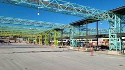
Overhead electrification of transit fleets typically includes similar elements from project to project; a series of pantographs that are supported from an overhead structure that accommodates signage, lighting, conduit runs, fire suppression and security elements. These structures are typically steel and are spaced at an interval that allows for either 40- or 60-foot buses to be charged in rows simultaneously.
The following areas were revised in collaboration with King County, Wash.
Loading criteria for an overhead gantry
All structures are designed for wind, seismic activity, snow, atmospheric ice and people loads. If you have a maintenance type structure or an office type facility, there is loading for storage and equipment. For an overhead gantry, these design standards don't apply.
We needed to determine what would be required to accommodate gantry members and elevated equipment platforms. In the case of an electrical charging yard, we need to support the following:
- Electrical equipment
- Distribution conduits
- Control boxes
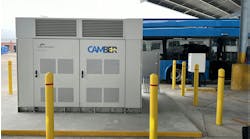
- Transformers
- Junctions to supply electricity
Some components are relatively light while others like the transformers are exceedingly dense. We determined a two-pronged approach.
- Uniform dead loads: Provide a uniform dead load allowance across the elements to support the known equipment and expected loads, ensuring an optimized and purposeful structural design.
- Live load: Mezzanines handle specific equipment loads, plus 40 psf live load to allow for future flexibility and safety.
Given procurement challenges, it was difficult to know in advance exactly what would be the final weights. We designed enough flexibility to accommodate the final selection. Future equipment will likely be lighter and smaller. We designed for today’s gravity loads and seismic force imparted by the transformers, essentially enveloping all future load combinations that were reasonable to expect.
Optimizing electrical charging yards with risk categories
Because the structure type is new, the team needed to define what performance standards are realistic. From a seismic standpoint, there's ambiguity on how to treat an electrical charging yard with respect to risk categories. Depending on your agency and what your expectations are for your facility, your requirements are going to vary.
For the gantry trusses, it's reasonable to assume that code minimum deflection criteria would be sufficient. However, the pantographs that are charging the buses only have so much capacity to tolerate structural movement.
This struck a balance between structural efficiency and maximizing pantograph operability. Any tighter deflection tolerance drove the weight of the gantry truss elements up or required deeper truss to achieve. Anything less and the structure was at risk. It took concerted effort to coordinate structural needs, costs and county requirements to arrive at this conclusion.
Designing gantry structures to sustain seismic activity
Based on the ASC E7 code, gantry structures for a charging yard would fall under a risk category 2 designation. That's only taking structure into consideration. It doesn't account for how the end user expects to operate the structure in an emergency.
The county felt it was important for the charging facility to be fully operational after a design level seismic effect. Designing the charging facility to meet immediate occupancy requirements for this risk category, per the code, would have imposed unnecessary additional costs and complexity on the structure and the design of the elements.
We did not want to solely meet the minimal requirements of risk category 2 design, so we developed Risk Category 2+. This level of performance permits the structure as a risk category 2 design but accounts for the increased loading and detailing requirements that are needed for a risk category 3 structure. In this way, we were able to deliver a cost-effective and efficient structure, but we're also able to address the concerns regarding seismic serviceability.
Ensuring structures support routine maintenance
The county wanted to ensure that it was easy for them to perform routine maintenance. This requirement influenced every aspect of the structural design. From a structural perspective, these requirements don’t really change the design and are relatively easy to accommodate, but they aren’t typical requirements. Investing time upfront to negotiate these additional needs and plan for the long-term maintenance and operation of the facility is well worth the effort.
Emphasizing sustainability through material selection
We explored sustainable design in several ways, the most common of which is to look at materials, such as recycled content in steel and cement content in concrete, and the overall volume of concrete. We determined ways that we could meet or exceed benchmark standards, but there’s more to sustainability than material standards. We can also minimize the number of elements in a structure and minimize complexity in the design, so that it requires less material overall.
It's important to outline criteria in the basis of design so that the structural engineer can accommodate these adjustments up front.
As a team, dive into the details of maintenance and operation needs in the initial planning phase. It’s important to evaluate the gaps in the code, the geographical nuances and sustainability goals.

Jeremiah Bowles | Principal at Lund Opsahl
Jeremiah Bowles, PE, SE, P.Eng., is a principal at Lund Opsahl. Jeremiah has over 17 years of structural engineering experience, spanning transit, civic, commercial, higher education and residential projects. With extensive experience collaborating with public transit agencies, his current projects include King County Metro Transit Interim Base Electrification, King County Metro Transit South Annex Base, Intercity Transit Pattison Base and TriMet Powell Base. Bowles understands the unique structural challenges of transit infrastructure, from facility modernization to electrification, and is committed to delivering innovative solutions. Known for his collaborative leadership, he ensures seamless coordination across disciplines to create efficient, future-thinking designs.


